How To Diagram Systems
Dr Milan Milovic provides a brilliant description for The C4 Model. Let’s take a look.
The C4 Model
When developing software, it is important to have a clear plan and understand how different components of the system will work together. Documentation and diagramming help us to achieve this by providing a 𝘃𝗶𝘀𝘂𝗮𝗹 𝗿𝗲𝗽𝗿𝗲𝘀𝗲𝗻𝘁𝗮𝘁𝗶𝗼𝗻 𝗼𝗳 𝘁𝗵𝗲 𝘀𝗼𝗳𝘁𝘄𝗮𝗿𝗲 𝗮𝗿𝗰𝗵𝗶𝘁𝗲𝗰𝘁𝘂𝗿𝗲. This helps different stakeholders, like developers, testers, and clients, to have a common understanding of the software design.
One of the preferred ways to visualize the software architecture is 𝘁𝗵𝗲 𝗖𝟰 𝗺𝗼𝗱𝗲𝗹, developed by Simon Brown, a software architect, and author. The C4 model examines a software system’s static structures containers, components, and code. And individuals use the software programs we create.
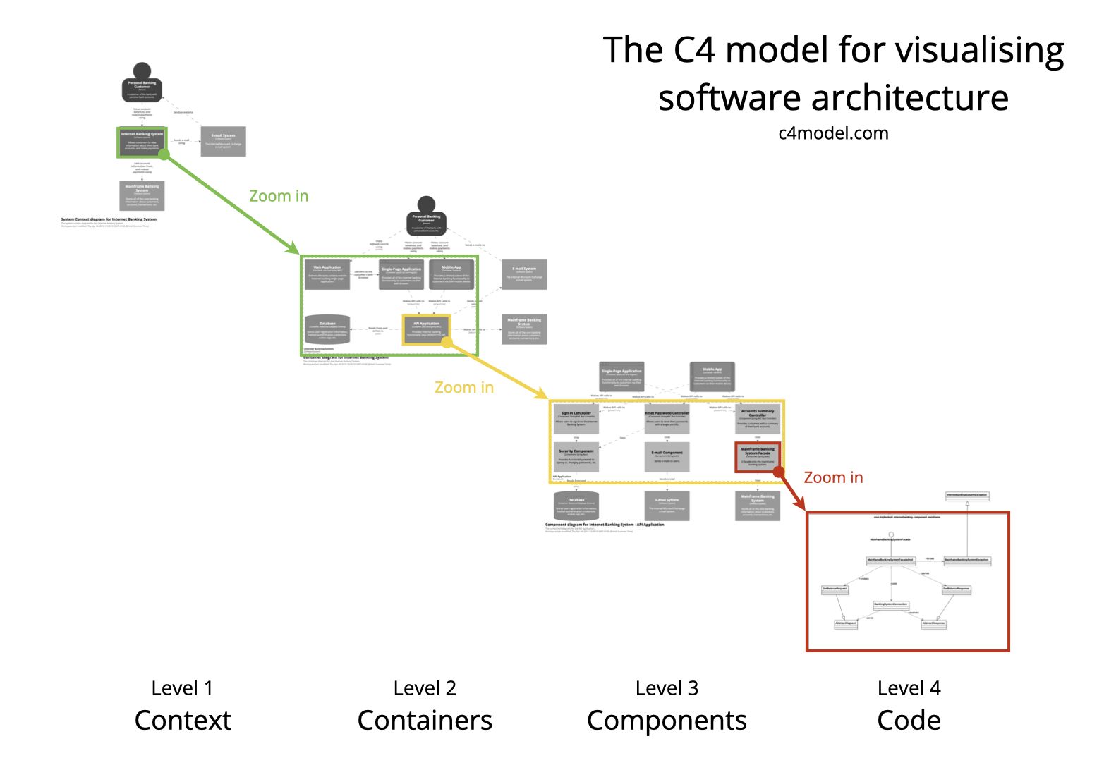
The C4 model consists of 𝗳𝗼𝘂𝗿 𝗹𝗲𝘃𝗲𝗹𝘀 𝗼𝗳 𝗮𝗯𝘀𝘁𝗿𝗮𝗰𝘁𝗶𝗼𝗻, which are represented by four different types of diagrams:
🔹 𝗖𝗼𝗻𝘁𝗲𝘅𝘁 (𝗟𝗲𝘃𝗲𝗹 𝟭): System Context diagram - This diagram shows the system in context, providing an overview of the system and its environment. The system here is the highest level of abstraction and it shows the system under consideration as a box in the center, surrounded by its users and other systems that interact with it. These diagrams help provide a big-picture overview.
🔹 𝗖𝗼𝗻𝘁𝗮𝗶𝗻𝗲𝗿𝘀 (𝗟𝗲𝘃𝗲𝗹 𝟮): Container diagram - This diagram shows the high-level components or services within the system and how they are connected. It shows each component as a box with its internal details abstracted away, which are separately deployable or executable. Containers can represent APIs, databases, file systems, etc.
🔹 𝗖𝗼𝗺𝗽𝗼𝗻𝗲𝗻𝘁𝘀 (𝗟𝗲𝘃𝗲𝗹 𝟯): Component diagram - This diagram shows the internal components of a container and how they interact with each other. Here we can visualize abstractions in our codebase. E.g. in C#, it is an implementation class behind some interface.
🔹 𝗖𝗼𝗱𝗲 (𝗟𝗲𝘃𝗲𝗹 𝟰): Code diagram - This diagram shows the detailed structure of a single component or module, including its classes and their relationships.
Most teams should at the very least produce and keep up-to-date 𝗰𝗼𝗻𝘁𝗲𝘅𝘁 𝗮𝗻𝗱 𝗰𝗼𝗻𝘁𝗮𝗶𝗻𝗲𝗿 𝗱𝗶𝗮𝗴𝗿𝗮𝗺𝘀 for their software system. If they are useful, component diagrams can be made, but for long-term documentation needs, you’ll need to figure out how to automate changes to these diagrams.
Image source: c4model. com.